Casting can produce strong, complex parts, but small process changes may create serious defects. A cool die, damp sand, or poorly placed riser can affect the final result. In practical foundry work, defects often appear as cracks, porosity, shrinkage cavities, inclusions, misruns, and dimensional distortion. Each one leaves different evidence on the casting surface or inside the metal.
So, what are the common defects in casting processes, and why do they occur? This guide examines the causes, visible signs, and suitable prevention methods for each problem. It considers factors such as metal temperature, mold permeability, pouring speed, alloy behavior, and solidification control. Inspection methods, including visual checks, radiography, ultrasonic testing, and dimensional measurement, can reveal issues that ordinary inspection misses. Experienced engineers usually compare defect patterns with process records rather than guessing from appearance alone. That approach is more reliable.
No process is perfect.
Even skilled teams can overlook a minor change in moisture, venting, or furnace practice. A clean surface may hide internal porosity. A stable production line may still produce occasional shrinkage after a tooling adjustment. Therefore, defect analysis should include production data, operator observations, material certificates, and inspection results. The goal is not merely to reject flawed castings. It is to understand the process, correct the underlying cause, and prevent the same failure from returning. Some explanations remain uncertain until testing confirms them. That uncertainty deserves attention, not convenient assumptions.
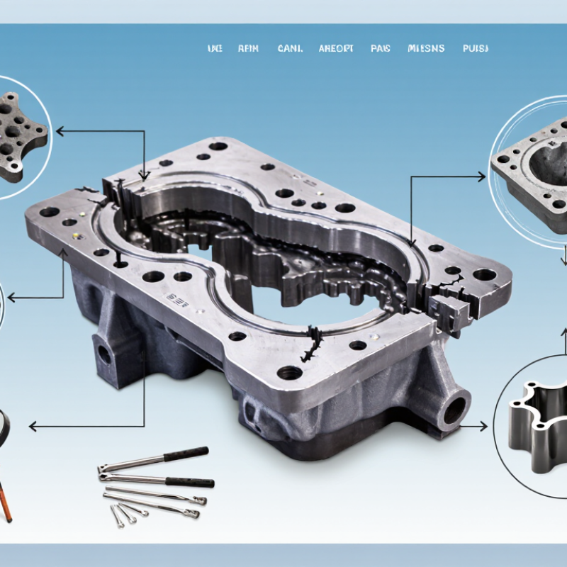
Casting defects become easier to control when classified by location, cause, and severity. ASTM E155 provides reference radiographs for evaluating discontinuities in aluminum and magnesium castings. It helps inspectors compare actual images with documented defect levels. However, it does not replace engineering judgment or project-specific acceptance criteria.
Location often reveals the process problem. Surface defects may include cold shuts, misruns, and exposed inclusions. Subsurface defects can appear as gas porosity or oxide films. Internal shrinkage commonly develops near thick sections, hot spots, and junctions where metal remains liquid longer. A cluster of rounded indications may suggest trapped gas. Irregular, jagged areas often point toward shrinkage or inclusions. Not always.
Cause and severity must be reviewed together. Gas porosity may result from moisture, excessive turbulence, or poor venting. Shrinkage usually relates to insufficient feeding during solidification. Inclusions can enter through dirty charge materials, damaged filters, or unstable melt flow. ASTM E155 reference images help classify the indication’s size, density, and distribution. A small isolated pore may be acceptable in one application but critical in a pressure-containing section. A larger defect near a machined surface may become harmless after removal, though that assumption needs evidence. Experienced inspectors record casting location, section thickness, defect pattern, and radiographic appearance before making a decision. This step is easy to rush. It should not be.
Gas porosity is a frequent defect in green-sand castings. It appears as small cavities, pinholes, or rounded holes inside the metal. These voids often result from trapped steam and poor gas escape during pouring. Green-sand moisture should remain roughly between 2% and 4%. That range is a practical starting point, not a universal rule. Sand type, binder content, grain size, and pouring temperature can change the ideal value.
Moisture testing should happen at regular intervals, not only after defects appear. A dry sand mix may lose strength and crack around the mold cavity. Excess moisture can generate more steam than the vents can release.
The result may be blowholes, rough surfaces, or weak sections. Operators should check the sand near the mixer and mold line, because moisture may not be evenly distributed. Ramming pressure also matters. Over-rammed sand can close gas pathways, even when moisture is controlled correctly.
In production trials, I would record moisture, permeability, metal temperature, and defect locations together. That simple record often reveals patterns. Still, moisture control alone will not solve every casting problem. Poor venting, contaminated sand, and turbulent filling may create similar symptoms. A 2–4% reading can look acceptable while the mold remains poorly prepared. Small adjustments, followed by sectioning and inspection, are usually more reliable than changing several variables at once.
Shrinkage is one of the most common defects in aluminum casting. During solidification, an aluminum alloy may undergo about 6–7% volume contraction. If liquid metal cannot feed this loss, cavities form inside the casting. These voids often appear near thick sections, junctions, and closed ends.
A practical diagnosis begins with the casting layout. Look for a dark, irregular cavity rather than a smooth gas pore. Radiographic inspection can reveal hidden shrinkage, while sectioning confirms its rough, branched surface. Check the riser position, pouring temperature, and local wall thickness. A hot spot that stays liquid after nearby metal has solidified is a strong warning sign. Poor directional solidification is often the real cause.
The remedy is not simply adding more metal. Risers must remain liquid long enough to feed contraction. Chills, redesigned transitions, and improved gating can guide solidification toward the riser. Process records also matter. Compare melt temperature, filling time, and mold temperature across rejected parts. A simple rule is useful, but not perfect. Alloy composition and casting geometry change the result. In practice, I would verify the suspected area twice before changing tooling. Some defects blamed on shrinkage are actually trapped gas or oxide-related porosity. That distinction matters.
During solidification, aluminum alloys typically undergo approximately 6–7% volumetric contraction. If the liquid metal is not adequately fed, this contraction can produce shrinkage cavities and shrinkage porosity.
The values represent the commonly cited engineering range for liquid-to-solid volumetric contraction in aluminum-alloy casting. Higher contraction increases the need for effective risers, directional solidification, and sufficient feeding paths.
What Are the Common Defects in Casting Processes?
Cold shuts and misruns often look similar, but their causes differ. A cold shut appears as a visible seam where two metal fronts meet without bonding. A misrun is incomplete filling, usually leaving rounded, unfilled edges. The AFS Casting Defects Handbook links both defects to insufficient heat and flow, but shop-floor evidence shows that geometry and venting can change the result. The World Foundry Organization’s 2023 World Casting Census reported global casting output above 100 million tonnes. That scale makes small process losses significant, yet the census does not identify defect causes. This limitation deserves attention.
Measure metal temperature at the furnace, ladle, and mold entry point. A falling temperature may expose a cold-shut risk before the casting looks defective. For misruns, compare temperature with fluidity results from a spiral test or thermal analysis. Low fluidity, thin walls, long flow paths, and slow filling commonly produce incomplete sections. A practical check is to inspect the defect surface. A cold shut often forms a sharp, linear mark. A misrun usually ends with a smooth, rounded contour. Still, this rule is not perfect. Oxide films can imitate a cold shut.
Tips: Record temperature loss during transfer, not only the pouring temperature. Check vents near the final filling area. Review fill time and gate size together. One reading is insufficient. In production troubleshooting, repeating the test under stable mold conditions is more reliable than changing several variables at once. Industry guidance from the AFS Casting Defects Handbook also supports controlled comparisons between fluidity, temperature, and filling behavior.
| Defect | Typical Appearance | Primary Mechanism | Temperature and Fluidity Indicators | Recommended Checks | Common Corrective Actions |
|---|---|---|---|---|---|
| Cold Shut | Linear seam, fold, or crack-like mark where two metal fronts meet without fully fusing. | Two partially solidified metal streams join after their oxide films or chilled surfaces prevent complete bonding. | Metal temperature is often marginal rather than extremely low. Flow becomes sluggish before the fronts meet, especially in thin sections or around sharp changes in direction. | Compare pouring temperature with the alloy’s normal liquidus-to-pouring range; inspect the meeting location and verify filling time, mold temperature, and runner balance. | Increase metal or mold temperature within the approved process window, improve gating and venting, reduce unnecessary flow interruptions, and smooth abrupt section changes. |
| Misrun | Incomplete casting with rounded, unfilled edges or missing extremities, ribs, or thin walls. | Metal freezes before the mold cavity is completely filled. | Insufficient superheat, excessive heat loss, or low fluidity. The temperature may fall below the required filling range before the last region is reached. | Measure melt temperature at the ladle or pour point, check mold and die temperature, review filling time, and perform a standardized fluidity or spiral-flow test when appropriate. | Use suitable pouring and mold temperatures, shorten transfer time, improve insulation, enlarge or reposition gates, and avoid excessively thin flow paths. |
| Cold Shot | Small rounded or elongated metal globules embedded in the casting surface or section. | Droplets or splashes oxidize and solidify separately before becoming properly integrated into the main metal stream. | Often associated with low fluidity, turbulent pouring, or a large temperature drop during transfer. | Review pouring practice, ladle handling, stream continuity, melt temperature, and evidence of turbulence or splashing in the gating system. | Pour steadily, reduce turbulence, maintain an appropriate metal temperature, and redesign gates or runners to promote smoother flow. |
| Shrinkage Cavity | Irregular internal or surface cavity, frequently located in a heavy section or hot spot. | Liquid metal contraction during solidification is not compensated by sufficient feed metal. | Usually linked more strongly to solidification and feeding conditions than to fluidity alone. Excessive local heat retention can increase the risk. | Review solidification simulation or thermal observations, identify hot spots, check riser effectiveness, and examine section thickness transitions. | Improve riser design, use chills or directional solidification, modify section geometry, and control pouring and mold temperatures. |
| Gas Porosity | Round or elongated internal voids with smooth walls; may be concentrated near the surface or in the upper regions of a casting. | Gas dissolved in the molten metal comes out of solution during solidification, or gas becomes mechanically entrapped. | High melt temperature can increase gas solubility in some alloys, while turbulent filling can entrain air. Fluidity may appear acceptable even when gas content is excessive. | Check melt cleanliness, hydrogen or dissolved-gas level where applicable, venting, vacuum performance, and turbulence in the filling system. | Improve degassing and filtration, reduce turbulence, maintain effective venting, and avoid unnecessary superheating or prolonged holding. |
| Inclusions | Nonmetallic particles, films, or dark irregular areas visible on a fractured or machined surface. | Oxides, slag, refractory fragments, or other foreign material becomes trapped in the casting. | Low fluidity can prevent inclusions from separating or floating out; turbulent flow can break oxide films into entrained defects. | Inspect melt surface condition, skimming practice, filters, refractory condition, and runner velocity; use metallographic examination when needed. | Improve cleaning and filtration, minimize turbulence, maintain clean ladles and tools, and optimize runner design. |
| Hot Tear | Rough, branched crack formed while the casting is still partly solid and unable to accommodate contraction. | Restricted contraction during late solidification creates tensile stress in weak, semi-solid regions. | Related primarily to solidification range, restraint, and thermal gradients rather than simply low pouring temperature. Excessive local hot spots may increase susceptibility. | Review alloy solidification behavior, mold restraint, core design, hot-spot locations, and cooling uniformity. | Improve casting geometry, reduce restraint, adjust risering and cooling, and use an alloy and process condition suitable for the design. |
| Sand Inclusion or Scab | Raised, rough, or irregular surface area containing mold material or a section of mold face lifted into the casting. | Mold or core material breaks away, erodes, or reacts with the molten metal. | High thermal loading, excessive metal velocity, poor mold strength, or inadequate refractoriness may contribute; low fluidity can make filling defects more pronounced. | Inspect mold hardness and permeability, examine coating condition, check gate velocity, and review metal temperature against the molding material limits. | Improve mold and core strength, repair coatings, reduce erosion-producing flow, and control pouring temperature and velocity. |
Note: Temperature limits and fluidity requirements vary by alloy family, section thickness, mold material, and casting method. Always compare readings with the approved process window for the specific alloy and equipment.
Casting defects are not always visible on the surface. Gas porosity, shrinkage cavities, cracks, and inclusions may remain hidden inside a component. Radiography provides a practical way to inspect these areas without cutting the casting apart.
ASTM E446 reference radiographs help evaluate discontinuities in steel castings across defined thickness ranges. ASTM E192 supports the examination of investment steel castings. Inspectors compare the production image with reference levels, while considering defect type, size, location, and concentration. Proper preparation matters. The casting surface should be clean, the X-ray system calibrated, and image quality indicators correctly positioned. Radiographs reveal hidden damage.
However, radiography does not prove that every casting is safe. Dense geometry, overlapping sections, and poor exposure settings can hide relevant indications. A single clean image can still mislead. Acceptance criteria should come from the drawing, purchase specification, or approved inspection plan, not personal judgment alone. ISO 8062 addresses dimensional and geometrical tolerances for castings, including tolerance grades and machining allowances. Measurements should check features such as wall thickness, hole position, flatness, and overall length. A casting may pass radiographic inspection but fail dimensional requirements. The opposite can also happen. Combining radiographic results with ISO 8062 measurements creates stronger evidence, although the inspection plan may still need revision when defects repeat. This reflective step is often missed.
A moisture range of roughly 2% to 4% is a practical starting point. It is not a universal rule. Sand type, binder content, grain size, and pouring temperature may require adjustments.
Excess moisture creates steam during pouring. If gas cannot escape, small cavities, pinholes, or rounded holes may form. Dry sand may lose strength and crack near the mold cavity.
Test it at regular intervals, not only after defects appear. Check samples near the mixer and mold line. Moisture may differ across the production area.
No. Poor venting, contaminated sand, turbulent filling, and excessive ramming can create similar problems. A suitable reading does not prove the mold is well prepared.
Over-rammed sand can close pathways needed for gas movement. Steam then remains trapped inside the mold. The moisture reading may still look acceptable.
A cold shut is a visible seam where two metal fronts meet without bonding. A misrun is incomplete filling with rounded, unfilled edges. The distinction is useful, but imperfect.
Measure metal temperature at the furnace, ladle, and mold entry point. Compare temperature with fluidity, fill time, wall thickness, and flow distance. One reading is insufficient.
Record moisture, permeability, metal temperature, fill time, and defect locations together. Inspect the final filling area and nearby vents. Change one variable at a time when possible. That is slower, but clearer.
Understanding what are the common defects in casting processes is essential for improving product quality, reducing waste, and selecting suitable inspection methods. Casting defects can be classified by their location, probable cause, and severity, with ASTM E155 providing a useful framework for evaluating discontinuities. Gas porosity is often associated with excessive moisture or poor venting in green sand, so maintaining moisture at roughly 2–4% can help limit trapped gases. Shrinkage defects should also be considered, especially in aluminum alloys, which may experience approximately 6–7% volume contraction during solidification.
Cold shuts and misruns are typically linked to insufficient metal temperature, poor fluidity, or interrupted mold filling. Comparing pouring conditions, flow behavior, and mold design can help distinguish between them. For defects that cannot be identified from the surface, radiographic inspection following ASTM E446 or ASTM E192 can reveal internal voids, inclusions, and incomplete fusion. Finally, ISO 8062 tolerances support dimensional verification, helping determine whether casting irregularities remain within acceptable manufacturing limits.

HYDRA CNC